 UniWave Electric
UniWave Electric
UniWave Electric
Converting a hand-operated motor switch can improve control, protection, and everyday safety. The key question is not simply how to upgrade an old manual starter to an automatic magnetic starter. It is whether the existing motor, wiring, enclosure, and operating environment can support the change. A qualified electrician should verify these conditions before any work begins.
The International Energy Agency reports that electric motor-driven systems consume about 46% of global electricity. Even small improvements in motor control can therefore influence operating efficiency and equipment reliability. A magnetic starter uses a contactor, overload relay, control circuit, and usually a start-stop station. Together, these parts allow remote operation and help disconnect the motor during overload conditions. The U.S. Department of Energy’s motor-system guidance also emphasizes correct motor protection, efficient controls, and proper maintenance. These recommendations matter in a workshop where dust, vibration, and repeated starting can weaken old components.
A careful conversion begins with the motor nameplate. Check voltage, full-load current, phase, frequency, and starting requirements. Then match the contactor and overload relay to those values, following IEC 60947-4-1 or applicable NEMA guidance. Confirm the control-transformer or coil voltage. A wrong coil can fail quickly.
Do not assume the old enclosure is suitable. Its terminals may be corroded, and its grounding path may be incomplete. Lockout procedures and local electrical codes remain essential. The upgrade is not automatically better. Poor sizing can create nuisance trips, overheating, or unsafe restarting. A documented inspection, functional test, and clear wiring diagram make the finished system more dependable. Mistakes are possible, so verify every connection twice.
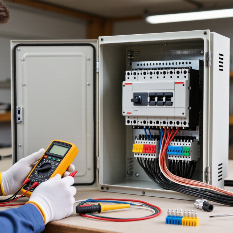
Before converting a manual starter, inspect the motor and its working environment. Record the nameplate voltage, phase, full-load current, horsepower, and service factor. Check the existing conductors for heat damage, loose terminals, and insulation wear. A dusty pump room may require a different enclosure than a clean workshop.
The magnetic starter must match the motor’s operating current and starting demand. Confirm that the overload protection suits the motor, not just the circuit breaker. Measure the available control voltage and identify every existing switch, stop button, float switch, or pressure control. Decide whether the motor needs maintained or momentary control. The choice affects the contactor coil and control wiring.
A qualified electrician should verify isolation, grounding, short-circuit protection, and local code requirements before modification. In field assessments, small details often change the design. A motor may start smoothly unloaded but trip when connected to a full pump. That possibility deserves a test plan. I have learned that old labels can be wrong. Recheck them with approved instruments and current documentation. Do not assume the manual starter’s enclosure, disconnect, or overload device can be reused. Sometimes replacement is safer and more economical. The assessment should also consider restart behavior after a power failure. Automatic restarting may create an unexpected hazard near moving equipment. Purposeful control is better than simply adding a coil.
Disconnect the upstream power supply completely. Open the isolating device, apply a lock, and attach a warning tag. Test the meter on a known live source. Check every phase, phase-to-phase, and phase-to-ground. Stored capacitor energy may remain dangerous.
Photograph the wiring before removing anything. Mark line conductors, motor conductors, overload wires, and control wires. Inspect loose terminals, heat damage, moisture, and brittle insulation. Old diagrams may be wrong. My first sketch might be wrong.
Check the motor nameplate current and available control voltage. Match the contactor, coil, overload relay, enclosure, and disconnecting means. Set overload protection near the rated motor current. Do not use a convenient guess.
A typical circuit uses a magnetic contactor and overload relay. It also needs stop and start buttons. An auxiliary holding contact keeps the starter energized. A pressure switch, float switch, or sensor can provide automatic control.
Route the supply through the contactor. Pass the motor conductors through the overload relay. Wire the overload’s normally closed auxiliary contact in series with the coil. Match the coil voltage to the control supply. Check it twice.
Keep the motor disconnected during the first control test. Verify zero voltage before handling conductors. Confirm that the stop button opens the control circuit. Operate the sensor manually and watch the contactor response. A signal can behave poorly under moisture.
Perform a brief bump test before normal operation. Check rotation, unusual noise, contact bounce, humming, and delayed release. Measure current on every phase after starting. Uneven readings may indicate loose connections, supply imbalance, or mechanical resistance.
Test the overload trip under controlled conditions. Never bypass it for convenience. Confirm that power restoration cannot start the motor unexpectedly. Recheck the system after warm-up. The first test may pass, yet vibration can expose weak wiring.
A qualified electrician should verify isolation and wiring before energizing. They should review grounding, terminal tightness, enclosure suitability, and protection settings. Record current readings and test results. A neat panel can still hide a poor control decision.
Converting a manual starter to an automatic magnetic starter begins with evaluating the existing motor, starter, voltage, current, phase configuration, and control requirements. The goal is to ensure the new system can handle the motor’s operating load while providing reliable starting and stopping control. This process explains how to upgrade an old manual starter to an automatic magnetic starter by selecting a compatible magnetic contactor, overload relay, control transformer or control circuit, push buttons, and any required sensing devices.
After disconnecting and verifying the power is isolated, the manual starter circuit can be prepared for modification. The magnetic contactor and overload relay are then installed, followed by careful connection of the power and control wiring according to the system design. Finally, all terminals, grounding connections, enclosure clearances, and overload settings should be checked before testing. A controlled test confirms correct start and stop functions, proper overload response, stable motor operation, and safe automatic control under normal working conditions.
