 UniWave Electric
In practical terms, both contactors and relays use an electrical signal to switch contacts. You may hear a click when a relay changes state inside a control panel. A contactor can make a similar sound while switching a motor or other substantial load. So, what is the difference between a contactor and a relay? The answer usually involves the load, switching frequency, and the device’s design—not just its size. A relay often handles control signals or lighter loads. A contactor is commonly designed for higher-current equipment and repeated switching. Not always.
The boundary is not perfectly neat. Some power relays handle demanding loads, while contactors vary by rating and application. Consider a workshop fan: its starting current may be much higher than its running current. Choosing a component by appearance alone can miss that detail. Check the manufacturer’s ratings for voltage, current, load type, and expected switching cycles. Also inspect the coil requirements and any listed arc-control features. Small details matter. The five tips in this guide explain how to compare these devices, read their specifications, and match one to a real application. They also point out common selection mistakes. A datasheet can feel less direct than a quick rule of thumb, and I sometimes find that frustrating. Still, careful checking is more dependable than assuming every relay is small or every contactor is large.
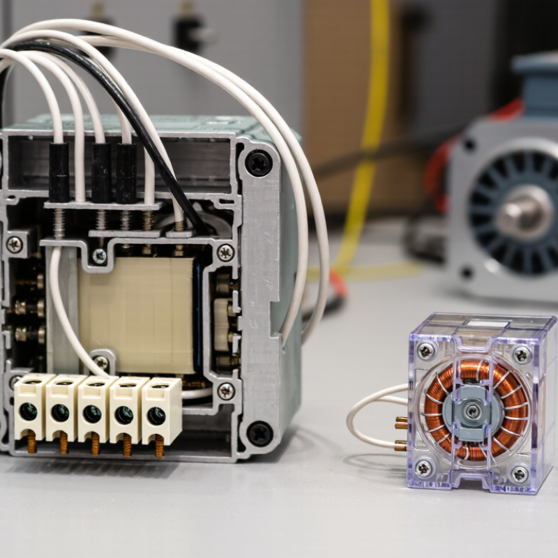
A contactor is an electrically operated switch built to control power circuits, often for motors, heaters, or lighting. When its coil receives a control signal, a magnetic field pulls an armature and closes the main contacts. You may hear a firm click. Some designs also use arc-control parts to manage the sparks created when contacts open under load. IEC 60947-4-1 covers contactors and motor-starters rated up to 1,000 V AC or 1,500 V DC. That scope is a useful reference, not a promise that every device suits every circuit.
A relay uses a similar switching idea, but many relays handle lower currents or control signals. In a control panel, a small relay might let a sensor signal switch a separate circuit. Electromechanical relays move contacts; solid-state relays switch electronically. IEC 61810-1 sets general requirements for electromechanical elementary relays, including electrical and mechanical testing. Ratings still matter. Check the load type, switching frequency, coil voltage, and contact rating before installation.
The distinction is practical, but not absolute. Some relays switch substantial loads, while contactors can appear in compact systems. A motor’s starting current may be much higher than its running current, so compare the device rating with real operating conditions. A label alone can mislead. Always consult the equipment documentation and applicable IEC specifications.
| Tip / Feature | Relay | Contactor | Practical tip |
|---|---|---|---|
| 1. Understand the basic function | An electrically operated switch. A control signal energizes a coil, moving contacts to open or close an electrical circuit. | Also an electrically operated switch, generally designed to switch power circuits and larger electrical loads. | Both use a control circuit to operate contacts; the key difference is usually the load and switching duty they are designed to handle. |
| 2. Match the device to the load | Commonly used in control, signaling, and switching applications, including some power loads when the relay is specifically rated for them. | Commonly used for loads such as motors, heaters, and lighting circuits when the contactor has the appropriate ratings. | Check the device’s rated voltage, current, load category, and application. A device’s name alone does not establish its capacity. |
| 3. Check contact design and arc handling | Contact size and arc-control features vary by relay type and rating. They must be suitable for the load being switched. | Power contactors often include features intended to manage the electrical arcs produced when switching higher-power loads. | Switching motors or other inductive loads can create demanding electrical conditions. Use equipment rated for the specific load and switching duty. |
| 4. Consider switching frequency and durability | Relays are available for different switching rates and electrical lives; performance depends on the design and the connected load. | Contactors are commonly selected for repeated power switching, but their electrical and mechanical life still depends on operating conditions. | Compare the manufacturer’s electrical-life and operating-duty specifications, especially for frequent starts, stops, or switching under load. |
| 5. Verify control and protection requirements | Coil voltage, contact arrangement, and any required suppression or protection depend on the relay and circuit. | Coil voltage and auxiliary-contact options vary. Motor circuits may also require separate overload and short-circuit protection. | Confirm coil compatibility and the complete protection scheme. A contactor by itself is not a substitute for overload or short-circuit protection. |
It uses an energized coil to close power contacts. You may hear a firm click.
Relays often switch signals or lighter loads. Contactors are generally designed for higher currents and frequent switching.
Some relays can handle substantial loads, but ratings vary. Check motor-starting current and the load category before choosing.
No. Coil voltage belongs to the control circuit. Contact ratings describe the load the device can switch.
Motors can draw much more current when starting than when running. Repeated starts may wear an unsuitable device quickly.
It may have wider contact spacing, arc-control parts, or auxiliary contacts. Overload protection is often separate.
No. An enclosure can reduce exposure to dust or accidental contact, but it cannot fix an inadequate rating.
No. Verify isolation using the appropriate procedure. I still find wiring diagrams easy to misread, so double-check them.
Compare load voltage, current, load type, switching frequency, and coil voltage with the equipment documentation. Small details matter.
Understanding what is the difference between a contactor and a relay starts with how each device switches an electrical circuit. Both use a control signal to open or close contacts, but they are designed for different operating demands. Contactors typically handle higher currents and larger loads, while relays are generally suited to lower-power control and switching tasks.
Their common applications, construction, and safety features reflect these differences. Contactors are often used to control motors, heating equipment, and other substantial loads, and may include features such as arc suppression and overload protection. Relays are commonly found in control panels and signal circuits, where compact size and precise switching are useful. Choosing between them depends on the circuit’s voltage and current, the type of load, switching frequency, installation conditions, and required protection. Selecting a device with suitable ratings helps support reliable and safe operation.
