UniWave Electric
A variable frequency drive overcurrent error can stop a production line without warning. The display may show OC during startup, acceleration, deceleration, or steady operation. The fault often feels simple. It rarely is.
If you are asking, “why is my variable frequency drive throwing an overcurrent error,” begin with the exact moment of failure. A trip during acceleration may indicate a short ramp, excessive load, or incorrect motor data. A trip during deceleration can involve regenerative energy or an unsuitable braking setup. A fault at constant speed may suggest a mechanical jam, damaged motor cable, phase imbalance, or internal drive trouble.
The investigation should combine experience with measured evidence. Record the drive model, fault code, motor nameplate values, output frequency, current, and operating conditions. Inspect the conveyor, pump, fan, or gearbox for binding. Look for hot terminals, loose connections, cracked insulation, and unusual motor noise. A reset is not a repair.
Power must be isolated safely, and the DC bus must discharge according to the manufacturer’s instructions. Only qualified personnel should perform electrical tests. Use the drive manual, not assumptions, when checking acceleration time, current limits, carrier frequency, overload settings, and motor autotuning. Even experienced technicians can misread a fault when they focus only on the inverter. The real cause may be upstream, mechanical, or intermittent. This guide explains a practical diagnostic path, while acknowledging one uncomfortable fact: the first suspected cause is often wrong.
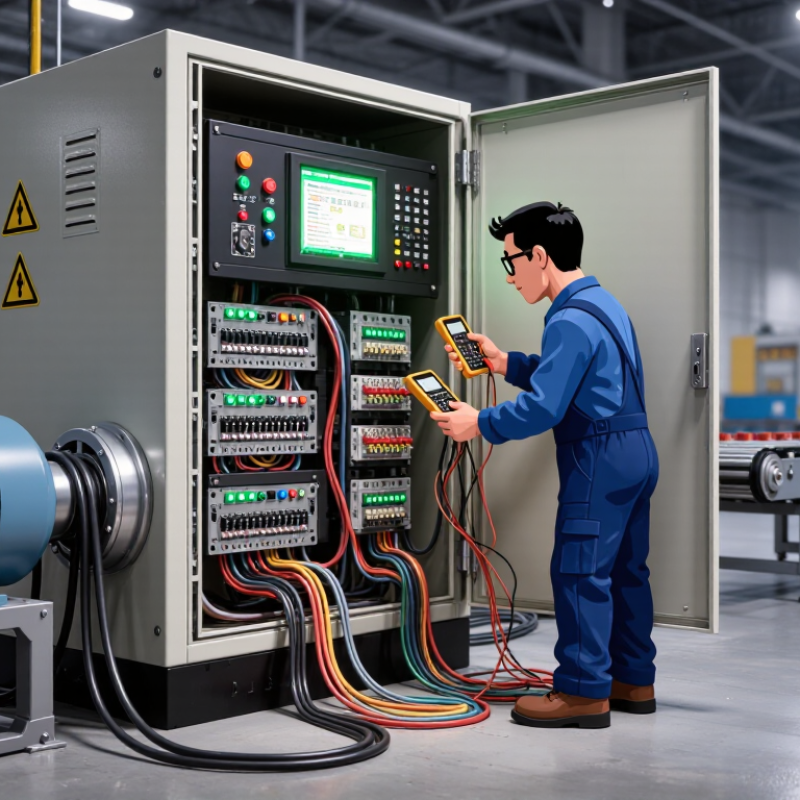
A variable frequency drive (VFD) overcurrent error means the motor is drawing more current than expected. The cause may be electrical, mechanical, or related to drive settings. In field service, I check the driven equipment before repeatedly resetting the drive. A jammed conveyor, seized bearing, blocked pump, or overloaded fan can create excessive torque. Short acceleration times can also demand a sharp current surge. If the motor starts normally but trips near full speed, inspect the load and acceleration profile carefully.
With power isolated, inspect motor terminals, cables, and cooling paths. Loose connections, damaged insulation, or phase imbalance can produce unstable current. Compare the motor nameplate data with the programmed voltage, frequency, and rated current. Incorrect values may cause poor control and unnecessary trips. I once blamed the drive and found a partially seized bearing instead. That mistake delayed the repair. Measure motor current on all phases, then compare the readings under similar load conditions. An uncoupled motor test can help separate drive problems from machine problems.
Tips: Record the exact fault code and operating speed. Increase acceleration time only after checking the load. Test the motor uncoupled when safe. Never bypass protective functions. Small details matter. A qualified technician should verify insulation resistance and mechanical condition before returning the system to service.
A variable frequency drive overcurrent error often begins with a simple wiring problem. Turn off power and follow the site’s lockout procedure before inspecting anything. Check motor terminals for loose strands, damaged insulation, or incorrect phase connections. A short between phases can trip the drive immediately. Test the motor cable and windings with suitable instruments, but disconnect the drive before insulation testing. Never guess around stored electrical energy.
Load conditions deserve equal attention. Review the drive’s fault history and compare motor current with the nameplate rating. A very short acceleration time can demand excessive current, especially when starting a loaded conveyor, pump, or fan. Increase acceleration gradually during testing. Do not hide the fault by raising the current limit. That may protect production briefly, but it can damage the motor or drive.
Mechanical components are easy to overlook. Check for a seized bearing, blocked impeller, tight belt, misaligned coupling, or jammed gearbox. With power isolated, rotate the machine by hand when safe. It should move smoothly, without grinding or stiff spots. I have found that a “drive problem” was sometimes a failing bearing. Still, this check is not perfect; intermittent faults can disappear when the machine is cold. Record current readings, temperatures, and operating conditions, then retest under the same load. A qualified technician should handle live measurements and any repair requiring panel access.
How to Fix a Variable Frequency Drive Overcurrent Error?
Reviewing drive parameters and motor control settings should be the first practical step. The U.S. Department of Energy’s Motor Systems Market Assessment reports that motor systems consume about 70% of industrial electricity. Incorrect settings can therefore waste energy and trigger repeated faults.
Check the motor nameplate against the drive’s programmed values. Confirm rated voltage, current, frequency, speed, and power. A current mismatch can make the drive protect the motor too early. Inspect the acceleration ramp next. A short ramp demands high torque immediately, especially with conveyors, pumps, or loaded fans. Increase the ramp gradually and observe the current trend.
Do not ignore the control method. V/f control may suit simple loads, while vector control often handles changing torque more accurately. Verify torque boost, slip compensation, current limits, and carrier frequency. Run the approved motor identification procedure only after confirming wiring and motor isolation. A rushed autotune can create worse results.
Watch the machine, not only the display.
If overcurrent appears during deceleration, the load may be returning energy. A longer deceleration time or suitable braking arrangement may help. Also inspect couplings, bearings, belts, and blocked shafts. I have seen parameter changes blamed for faults caused by a seized bearing. That assumption delayed the repair. Record each adjustment, measure motor current under real load, and compare it with the nameplate rating. The U.S. Department of Energy’s Industrial Motor Systems guidance supports measurement-based maintenance rather than guesswork.
| Review Area | Parameter or Condition | Typical Reference or Check | Overcurrent Risk | Recommended Corrective Action | Expected Result |
|---|---|---|---|---|---|
| Motor nameplate data | Rated voltage, current, frequency, speed, and power | Values entered in the drive should match the motor nameplate. Motor rated frequency is commonly 50 or 60 Hz, depending on the motor and application. | High | Compare every motor data field with the physical nameplate. Correct mismatched values before running the motor again. | The drive can calculate motor voltage, current, and slip more accurately. |
| Motor overload setting | Electronic thermal overload current | The setting is normally based on the motor rated current, subject to the motor manufacturer's instructions and applicable electrical standards. | High | Do not increase the overload setting simply to prevent trips. Verify the motor rating, cooling method, load, and wiring first. | Protection remains effective while nuisance overload trips are reduced. |
| Acceleration time | Ramp-up time from zero speed to the commanded frequency | A very short acceleration time can demand more torque and current than the drive or motor can provide. | High | Increase the acceleration time gradually, especially for high-inertia loads such as fans, pumps, conveyors, and centrifuges. | Starting current and mechanical stress are reduced during acceleration. |
| Deceleration time | Ramp-down time from operating speed to stop | A short deceleration time can cause regenerative energy to flow back into the drive, which may produce an overvoltage or overcurrent condition. | Medium | Increase the deceleration time or use an approved braking method when the application requires rapid stopping. | Stopping becomes more stable and regenerative energy is better controlled. |
| Control mode | Volts-per-hertz, sensorless vector, or closed-loop vector control | Control mode must be suitable for the motor type, feedback arrangement, and load characteristics. | High | Select the appropriate motor-control mode. Perform motor identification or autotuning only when the motor is safely disconnected or stationary as required by the drive instructions. | Torque production and current regulation improve across the operating range. |
| Motor autotune | Static or rotating motor identification procedure | Autotuning measures motor characteristics used by vector-control algorithms. The correct procedure depends on the drive and motor installation. | Medium | Confirm that the motor is correctly wired and mechanically safe. Run the approved autotune procedure after entering accurate nameplate data. | The drive obtains more accurate motor model parameters and may control current more effectively. |
| Current limit | Maximum output current allowed during acceleration or load changes | A current limit set too low can cause poor acceleration or stalling; a limit set too high can overstress the motor and drive. | High | Use the drive's documented default or application guidance. Do not raise the limit beyond the drive, motor, or wiring ratings. | The drive manages temporary current demand without defeating overload protection. |
| Torque boost | Additional low-speed voltage or torque compensation | Excessive manual torque boost can increase motor current and heating, particularly when the motor is lightly loaded. | Medium | Return torque boost to the recommended default or reduce it incrementally while checking low-speed starting performance. | Low-speed operation remains sufficient without unnecessary magnetizing current. |
| Motor rotation and phase sequence | Motor direction and output phase connections | Incorrect phase connections can cause unexpected rotation, unsuitable load behavior, or mechanical interference. | High | Stop the system, isolate power, and verify the motor leads and commanded direction. Never change output wiring while the drive is energized. | The motor rotates in the intended direction and the load operates safely. |
| Motor cable and terminals | Loose terminals, damaged insulation, incorrect cable size, or excessive cable length | High-resistance connections and cable faults can create current imbalance, heating, or unstable motor operation. | High | With power isolated, inspect and tighten connections according to the equipment instructions. Check insulation and cable condition using qualified procedures. | Current becomes more balanced and electrical losses are reduced. |
| Motor insulation and winding condition | Shorted turns, phase-to-phase faults, or phase-to-ground leakage | A damaged motor can draw excessive or unbalanced current even when drive parameters are correct. | High | Have a qualified technician test the motor and cable separately. Repair or replace defective components before resetting the fault repeatedly. | The underlying electrical fault is removed instead of being masked by parameter changes. |
| Mechanical load | Overloaded, jammed, seized, or misaligned driven equipment | Excessive torque demand commonly causes high output current during startup or speed changes. | High | Inspect bearings, belts, couplings, gearboxes, pumps, fans, and conveyors. Confirm that the load can rotate freely before restarting. | Motor current returns closer to the normal operating range. |
| Operating frequency and speed reference | Commanded frequency above the motor or machine operating range | Excessive speed can increase mechanical load, reduce available torque, or create unsafe machine conditions. | Medium | Verify minimum and maximum frequency limits, preset speeds, analog reference scaling, and fieldbus commands. | The motor operates within its rated and application-approved speed range. |
| Low-speed cooling | Motor thermal performance at reduced speed | Many self-cooled motors provide less airflow at low speed, even when the drive output current is within its programmed limit. | Medium | Check the motor cooling requirements. Use an auxiliary fan or derate the motor when continuous low-speed, high-torque operation is required. | Motor temperature remains within the permitted operating range. |
| Fault history and trend data | Frequency, output current, load, and operating state at the time of the trip | A fault during acceleration suggests a different cause from a fault at steady speed or during deceleration. | Low | Record the fault code and operating conditions. Compare current at startup, steady state, and speed changes before modifying multiple parameters. | Troubleshooting becomes evidence-based and repeat faults are easier to isolate. |
An overcurrent error needs a safe, measured investigation. Stop the machine and isolate all power sources before opening the enclosure. Follow site lockout procedures, then verify zero voltage with a properly rated meter. The drive’s DC bus can remain charged after shutdown. Wait for the manufacturer’s stated discharge time, and confirm it with the meter. Never rely on indicator lights alone.
Inspect the motor leads for crushed insulation, loose terminals, moisture, or damaged conduit. Check for phase-to-phase and phase-to-ground faults using suitable test equipment. An insulation test can reveal hidden cable damage, but disconnect sensitive drive electronics before testing. Test the motor separately when practical. Compare winding resistance between phases. Small differences may deserve attention. Large differences suggest a motor or connection problem.
Review the drive settings against the motor nameplate. Incorrect acceleration time, excessive load, or a low-speed mechanical jam can trigger overcurrent. Rotate the shaft only when the equipment is safely isolated. Examine couplings, belts, bearings, and the driven load for binding. Check fuses, circuit breakers, contactors, and overload devices for correct ratings and signs of heat damage. Protection devices should not be bypassed to keep production moving.
Use current measurements during a controlled restart, with guards installed and qualified personnel nearby. Increase speed gradually and watch each phase. Record the fault conditions instead of resetting repeatedly. A rushed reset can hide a worsening failure. If readings conflict, stop and reassess the test setup. Incomplete measurements are still clues, but they are not proof.
A variable frequency drive overcurrent fault needs careful diagnosis, not repeated resets. Stop the drive and follow the site’s electrical isolation procedure. Check the fault history before clearing it. Look for sudden current spikes, high load conditions, or repeated trips during acceleration. Inspect the motor shaft, coupling, gearbox, and driven equipment for binding. A blocked conveyor or seized bearing can create an immediate overload.
Review the acceleration and deceleration times. A ramp that is too short may demand excessive torque from the motor. Increase the ramp gradually, then test the machine under normal load. Confirm motor voltage, current, frequency, and power settings match the nameplate. Incorrect values can distort protection and control. Measure phase-to-phase resistance and inspect insulation with suitable test equipment. Unequal readings deserve further investigation.
I once saw a fault blamed on the drive, but a damaged coupling was the real cause.
Prevention depends on routine evidence, not assumptions. Record normal motor current during startup and steady operation. Compare future readings against that baseline. Keep cooling paths clear, because heat can reduce operating margin. Inspect terminals for looseness, discoloration, or vibration damage. Use appropriate current limits and braking equipment for demanding loads. Check mechanical alignment after maintenance. Train operators not to bypass alarms. That shortcut often hides a developing failure. Environmental changes also matter, and an old parameter set may not suit a modified machine. Recheck settings after every motor or load change.
It means the motor is drawing more current than expected. The cause may be electrical, mechanical, or related to drive settings. Not always the drive.
Check for a jammed conveyor, seized bearing, blocked pump, overloaded fan, or binding gearbox. Inspect the shaft and coupling for resistance. Small details matter.
A very short acceleration ramp can demand excessive torque. Increase the ramp gradually after checking the load. Do not guess.
Inspect motor terminals, cables, insulation, and cooling paths. Look for loose connections, damaged insulation, discoloration, or blocked airflow. Keep hands away from energized parts.
Compare programmed voltage, frequency, and rated current with the motor nameplate. Incorrect values can reduce control quality and cause unnecessary trips.
Test the motor uncoupled when safe and permitted. Measure current on all phases under similar conditions. Unequal readings need investigation.
Record the exact fault code, operating speed, load condition, and trip timing. Note whether the fault happens during acceleration or near full speed. The pattern helps.
Record normal startup and running current as a baseline. Keep cooling paths clear, inspect terminals, and verify alignment after maintenance. Recheck settings after any motor or load change.
No. Stop the drive and follow the site isolation procedure. Check the fault history and inspect the equipment before resetting. Repeated resets can hide damage.
A variable frequency drive overcurrent error indicates that the drive is detecting more current than expected, often because of excessive mechanical load, motor wiring problems, incorrect settings, or a fault within the motor or drive system. If you are asking, “why is my variable frequency drive throwing an overcurrent error,” begin by inspecting the motor cables, terminals, grounding, and insulation. Check whether the driven equipment is jammed, overloaded, misaligned, or difficult to start. Mechanical issues such as worn bearings or blocked components can also increase torque demand and trigger the fault.
Next, review the drive’s motor data, acceleration and deceleration times, current limits, control mode, and protection settings. Safely test the motor, drive, and protective devices using appropriate procedures and qualified personnel. Correct loose connections, remove mechanical obstructions, adjust unsuitable parameters, or repair damaged components. To prevent future faults, maintain the equipment regularly, monitor operating current, keep the motor properly cooled, and record recurring fault conditions for early diagnosis.
