UniWave Electric UniWave Electric

How to Prevent Premature Failure in Electronic Switches?

Time:2026-09-30 Author:Sienna
0%

Electronic switches rarely fail without a story behind them. A control panel may look clean, yet microscopic dust, moisture, or oxidized contacts can quietly increase resistance. Over time, that resistance creates heat. Heat changes materials, weakens springs, and accelerates contact damage.

Understanding what causes premature failure in electronic control switches requires more than checking the switch after failure. Michael Pecht, an electronics reliability researcher and founder of the Center for Advanced Life Cycle Engineering, often stresses, “Reliability must be designed in, not tested in.” His point is practical: a switch cannot become reliable through final inspection alone. Its load, enclosure, wiring, environment, and installation must work together.

Consider a machine operating near a hot motor. Each switching cycle may produce a tiny arc across the contacts. Thousands of cycles later, the contact surface can become rough or welded. Vibration may loosen a terminal. Poor sealing may allow condensation inside the housing. An oversized current load can produce similar damage faster.

Small details matter.

Manufacturers should review electrical ratings under real conditions, not ideal laboratory conditions. They should test temperature cycling, humidity, vibration, switching frequency, and abnormal loads. Engineers also need to examine user behavior, because excessive force or incorrect wiring can defeat a well-designed component.

No prevention method is perfect. That is worth admitting. Field data may reveal failure patterns that laboratory testing missed. Regular inspection, thermal checks, secure connections, and suitable protection circuits can still extend service life. Reliable switch design begins with evidence, careful application, and a willingness to question convenient assumptions.
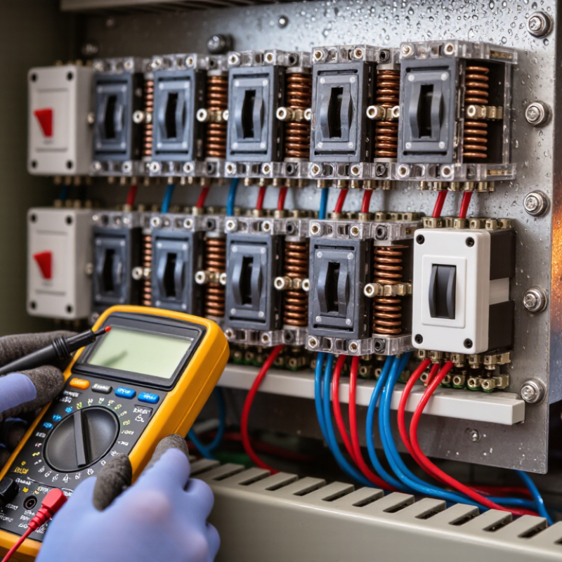
How to Prevent Premature Failure in Electronic Switches?

Understand Common Causes of Premature Electronic Switch Failure

Electronic switches rarely fail without warning. Their damage usually begins with heat, excessive current, moisture, or mechanical stress. A load exceeding its rated current can create hot spots inside contacts or semiconductor junctions. Frequent switching may also produce electrical arcs and voltage spikes. Poor ventilation traps heat, while dust and condensation encourage leakage paths. Loose terminals add resistance. That small resistance becomes a dangerous heater. Vibration can then turn a minor connection problem into an intermittent fault.

Reliable prevention starts with understanding the real operating environment. Measure the load during startup, not only during normal operation. Motors and transformers can draw several times their running current. Use suitable protection against surges, and allow a safe temperature margin below the maximum rating. Check terminal torque, solder joints, enclosure airflow, and cable strain. An oscilloscope can reveal brief spikes that a standard meter misses. Still, testing is not perfect. A clean bench result may hide failures caused by heat, vibration, or humidity in the field.

Tips: Keep a maintenance log with temperature, current, switching frequency, and failure timing. Inspect discolored terminals and cracked solder before replacing the switch. Separate sensitive signal wiring from noisy power conductors. Add cooling or electrical suppression only after confirming the actual fault. Replacing parts repeatedly is tempting, but it often leaves the original cause untouched. A simple inspection checklist helps, though technicians sometimes overlook the smallest loose connection.

How to Prevent Premature Failure in Electronic Switches?

Junction temperature is one of the most important factors affecting electronic switch reliability. The chart shows the calculated acceleration factor for thermally activated failure mechanisms at different junction temperatures, relative to 25°C.

The calculation uses the Arrhenius relationship with an activation energy of 0.7 eV. Higher junction temperatures can significantly accelerate aging, so designers should improve heat dissipation, maintain voltage and current margins, control switching transients, protect against contamination and moisture, and inspect solder joints for thermal-mechanical stress.

Select Switches That Match the Electrical and Mechanical Requirements

An electronic switch can fail early when its ratings only barely match the circuit. Check the maximum voltage and current, including brief startup surges, not just normal operating values. A motor may draw several times its running current for a moment. That short spike can pit contacts or overheat a small switch. Leave a sensible margin, and confirm whether the published rating applies to resistive or inductive loads. The distinction matters.

Mechanical fit matters just as much. Compare the actuator travel, mounting dimensions, terminal style, and expected operating force with the equipment around it. A panel switch that rubs against its enclosure may bind after repeated use. In a handheld device, a tiny actuator can also be awkward with gloves. Measure the cutout and check clearance before ordering parts; a drawing can look right while the real assembly disagrees.

Consider how often the switch will cycle and where it will operate. Dust, vibration, moisture, and temperature changes can shorten service life, even when electrical ratings look adequate. Match the enclosure protection and rated mechanical life to the actual environment. Test a sample in the finished assembly, under realistic load, and inspect the contacts after repeated operation. I have seen teams skip that step to save time. It is tempting, but the shortcut can hide a poor fit or a warm terminal until the equipment is already in use.

Control Heat, Current, Voltage, and Electrical Stress

How to Prevent Premature Failure in Electronic Switches?

Control Heat, Current, Voltage, and Electrical Stress

Premature failure in electronic switches rarely begins with one dramatic event. It often starts with slightly excessive heat during repeated operation. Measure the case temperature after the circuit reaches its normal working rhythm. A cool startup reading can be misleading. Check the hottest point near the switch, not only the surrounding air. Improve heat removal with wider copper areas, shorter thermal paths, and suitable cooling hardware. Keep the junction temperature below the rated limit, with practical safety margin.

Current deserves equal attention. A motor, relay, or transformer can draw a sharp inrush pulse before settling. Compare that pulse with the switch’s continuous and peak current ratings. Use a current probe when possible. Guessing is risky. Voltage spikes create another hidden threat, especially with inductive loads. Add an appropriate clamp, snubber, or flyback path, then verify the waveform with an oscilloscope. The spike should remain controlled during turn-off.

Electrical stress also depends on switching speed and circuit layout. A long trace can add unwanted inductance and produce ringing. Place control components close to the switch and keep high-current loops compact. Select gate resistance carefully; excessive speed may increase noise, while slow switching can create more heat. I have seen a design pass a short bench test and fail after several days. That experience changed my testing habits. Test under heat, load variation, and repeated cycles, because real circuits are rarely as polite as laboratory conditions.

How to Prevent Premature Failure in Electronic Switches? - Control Heat, Current, Voltage, and Electrical Stress

Stress Factor How It Can Cause Failure Preventive Design Practice What to Check
Excessive heat High junction or contact temperature can accelerate material aging, increase leakage, and reduce the switch’s service life. Estimate losses at the actual operating current and switching frequency. Provide suitable PCB copper, heatsinking, airflow, and thermal margin; follow the device’s temperature derating guidance. Measure temperature under worst-case ambient and load conditions. For semiconductor devices, keep junction temperature within the limits specified in the datasheet.
Overcurrent Excess current creates resistive heating. Repeated overloads or high inrush current can damage semiconductor junctions, contacts, or internal bond wires. Select a switch for the load’s steady-state and transient current. Account for inrush, motor starting, capacitor charging, and the switch’s safe operating area where applicable. Compare measured peak and continuous current with the device ratings and applicable derating curves. Verify the current protection device clears faults as intended.
Inductive-load interruption When current through an inductive load is interrupted, stored magnetic energy can produce a voltage spike that overstresses the switch. Use an appropriate flyback diode, TVS device, snubber, or other clamp suited to the load and switching requirements. Place suppression close to the load or switching path as appropriate. Use an oscilloscope to check the switch-node voltage during turn-off, including at maximum load current and under relevant operating conditions.
Overvoltage and transients Supply surges, switching spikes, or electrostatic discharge can exceed voltage limits and cause immediate or cumulative damage. Keep normal and transient voltages within the specified ratings. Choose suitable clamping and filtering components, and minimize parasitic inductance in high-current paths. Check maximum supply variation and transient levels against the datasheet’s absolute maximum ratings and the system’s surge or immunity requirements.
Excessive switching stress Frequent switching and operation during voltage-current overlap can increase losses and temperature, especially in power semiconductors. Confirm the device is suitable for the required switching frequency, load type, and switching mode. Follow specified gate-drive or control requirements and observe safe operating area limits. Review switching waveforms, switching frequency, and calculated switching losses at worst-case supply, current, and temperature.
Contact arcing and unsuitable load rating Mechanical contacts can arc when opening or closing loads. A resistive-current rating may not represent performance with motors, lamps, or other inrush-producing loads. Select contacts using the manufacturer’s rating for the actual load type and switching duty. Use appropriate suppression where permitted by the application and device specifications. Verify the load category, inrush current, operating cycles, and electrical life requirements against the switch’s specified ratings.
Poor PCB layout or connections Long, narrow, or high-resistance paths can add voltage drop and heat; parasitic inductance can also increase switching overshoot. Use conductor width and copper thickness appropriate to current and temperature rise. Keep high-current loops compact and ensure terminals and solder joints are designed for the load. Inspect the layout and measure voltage drop and temperature at connectors, traces, and the switch during representative worst-case operation.
Insufficient fault protection Short circuits, stalled loads, or component faults can expose the switch to damaging current or energy for too long. Coordinate fuses, circuit breakers, current limiting, or electronic protection with the switch’s ratings and the expected fault conditions. Test relevant fault scenarios safely and confirm that protection operates within the device’s allowable current, voltage, and energy limits.

Install, Operate, and Maintain Switches Correctly

Premature electronic switch failure often begins during installation. A switch can look secure while its terminal remains loose. Use the manufacturer’s specified torque, conductor size, and stripping length. Over-tightening can damage terminals. Under-tightening creates resistance and heat. Keep control cabinets clean, dry, and free from metal filings. Leave enough airflow around heat-producing components. The U.S. Bureau of Labor Statistics recorded 145 workplace deaths involving electrical exposure in 2022. Safe installation protects equipment and people.

Operation matters just as much. Do not exceed the rated voltage, current, switching frequency, or inductive load. Motors, solenoids, and transformers can create voltage spikes during switching. Suppression devices can reduce this stress when correctly selected. Avoid forcing a switch through a jammed mechanism. Repeated overloads may leave no visible damage at first. The IEC 60947 series emphasizes coordination between switching devices, loads, and protective equipment. In practice, incorrect application remains an easy mistake.

Maintenance should be scheduled, not improvised after failure. Inspect terminals for discoloration, looseness, dust, and cracked insulation. Record operating temperature and unusual noise. A thermal camera can reveal hot connections before contact damage becomes obvious. For critical circuits, measure contact resistance during planned shutdowns. NFPA 70B now treats electrical maintenance as a formal safety practice. Still, a checklist is not enough. Conditions change. Review load patterns, cleaning methods, and failure records every year. One missed inspection can undo careful installation.

Test Switch Performance and Detect Early Warning Signs

How to Prevent Premature Failure in Electronic Switches?

Test Switch Performance and Detect Early Warning Signs

A switch can feel normal while its contacts are already degrading. Test samples under the actual voltage, current, and load type they will face in service. IEC 61058-1:2016 sets out switch endurance tests, with operating cycles and conditions determined by the switch’s classification and rating. Use the applicable specification rather than treating one cycle count as universal. Record contact resistance, insulation resistance, and operating force before and after cycling. A rising resistance trend matters: it can signal contact wear, contamination, or a weakening connection before intermittent operation becomes obvious.

Look for changes during testing. A slow response, inconsistent click, visible discoloration, or a warm terminal deserves investigation. Measure temperature under load with a thermocouple, and inspect for loose joints after vibration or repeated operation. Compare results across several samples; one switch may behave differently from the rest. Small variations count. Keep a log of cycle count, load, ambient temperature, and each measurement, then repeat tests after exposure to heat, dust, or moisture expected in the product’s environment. If a result sits near the limit, do not dismiss it as noise. Recheck the setup and the sample. That extra test may feel excessive, but skipping it can hide an early failure pattern.

FAQS

How should I choose an electrical switch rating?

Check maximum voltage and current, including brief startup surges. Leave practical safety margin. Confirm whether the rating applies to resistive or inductive loads. A motor may briefly draw several times its running current.

Why can a motor damage a switch with a suitable current rating?

Motor startup creates an inrush pulse before normal operation begins. This pulse can pit contacts or overheat a small switch. Compare continuous and peak ratings with measured current, not guesses. Use a current probe when possible.

Which mechanical details should I check before ordering a switch?

Compare actuator travel, mounting dimensions, terminal style, and operating force. Measure the panel cutout and surrounding clearance. A drawing may look correct while the assembled enclosure disagrees. Test the actuator with gloves if the device is handheld.

How can the operating environment shorten switch life?

Dust, vibration, moisture, and temperature changes can reduce service life. Match enclosure protection and mechanical life to the real environment. A clean workshop test proves little. Inspect the switch after repeated operation in the finished assembly.

How do I control heat around an electronic switch?

Measure the hottest area near the switch after normal operation stabilizes. Startup readings can be misleading. Use wider copper areas, shorter thermal paths, or suitable cooling hardware. Keep junction temperature below its rated limit with extra margin.

How can I reduce voltage spikes from inductive loads?

Add a suitable clamp, snubber, or flyback path. Check the turn-off waveform with an oscilloscope. The voltage spike should remain controlled. Do not assume a short bench test reveals every transient problem.

Can circuit layout affect switch reliability?

Yes. Long traces add inductance and may cause ringing. Keep high-current loops compact and place control components close to the switch. Select gate resistance carefully. Excessive speed can increase noise, while slow switching can increase heat.

What testing method gives the most realistic result?

Test a sample in the completed assembly under realistic load. Include heat, load variation, startup surges, and repeated cycles. Inspect contacts and terminals afterward. A quick bench test can fool you. I have trusted one before, and it was not enough.

Conclusion

Preventing premature failure in electronic switches starts with understanding what causes premature failure in electronic control switches. Common contributors include excessive heat, electrical overload, voltage spikes, unsuitable switching capacity, mechanical wear, contamination, and poor installation. Choose a switch that matches the application’s current, voltage, load type, operating environment, and expected mechanical life. Proper sizing helps reduce stress on contacts and internal components.

Reliable performance also depends on correct installation, careful operation, and routine inspection. Keep connections secure, provide adequate heat dissipation, and avoid exposing switches to conditions beyond their rated limits. Regularly test switching behavior and look for early warning signs such as inconsistent operation, unusual heating, noise, or visible wear. Addressing these issues promptly can help prevent unexpected failure, extend service life, and improve the reliability of the equipment the switch controls.

Sienna

Sienna

Sienna is a skilled marketing professional with a deep expertise in our company’s core products and services. With a passion for innovation and detail, she plays a pivotal role in crafting insightful blog posts that not only highlight the unique features of our offerings but also provide valuable......