 UniWave Electric
UniWave Electric
UniWave Electric
A motor control center can look like a wall of symbols, numbers, and crowded conductors. Yet every mark carries operational meaning. Learning how to read a wiring diagram for a motor control center helps technicians trace power, control logic, grounding, and protective devices with greater confidence.
The need is practical, not academic. OSHA reports that electrical hazards cause more than 300 workplace deaths and approximately 4,000 injuries in the United States each year. NFPA 70E also stresses electrically safe work practices, risk assessment, and proper labeling before equipment interaction. These figures do not describe every MCC incident. They still reveal the consequences of careless interpretation. A single misunderstood contact can leave a starter energized when it appears inactive.
John Cadick, an electrical safety author and engineer, offers a useful warning: “Electricity is a very useful servant, but a very dangerous master.” His words fit diagram reading surprisingly well. Begin with the drawing title, voltage, and revision number. Then follow the incoming power path, branch protection, overload relay, contactor coil, and control return. Look for terminal numbers, wire tags, interlocks, and normally open or closed contacts. Trace with a finger, not a guess.
Real diagrams are rarely perfect. Older MCC drawings may contain faded labels, handwritten changes, or missing revisions. That uncertainty deserves attention. This guide explains how to compare schematic and wiring views, verify field connections, and test assumptions against safe procedures. The goal is not merely reading symbols. It is understanding what the motor will do before anyone touches the enclosure.
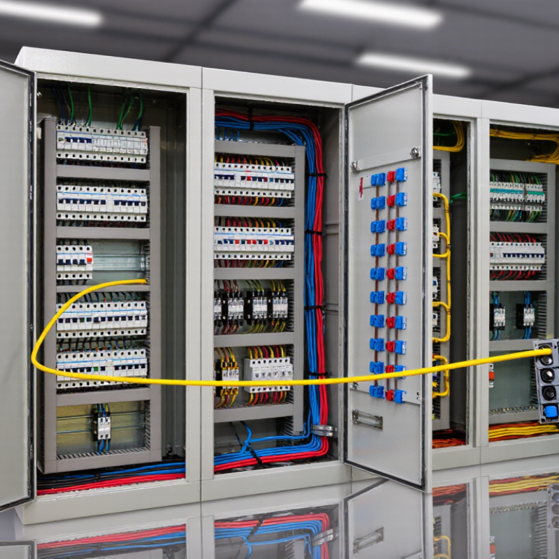
A motor control center diagram becomes clearer when you divide it into functional sections. Start with the incoming power section. It shows the main disconnect, power conductors, grounding path, and protective devices. Trace the lines toward the horizontal busbars. These bars distribute power to individual feeder compartments. Heavy lines usually represent power circuits, while thinner lines often show control wiring. Confirm this convention in the drawing legend.
Each feeder section may include a circuit breaker, contactor, overload relay, motor terminals, and local control devices. Look for the motor starter symbol and follow its connections carefully. The control circuit often includes stop and start pushbuttons, auxiliary contacts, relays, and an emergency stop connection. Terminal blocks mark the transition between internal wiring and field cables. Numbered wires help you follow a circuit across separate pages. I once misread an auxiliary contact because I focused on its symbol, not its reference number. That small mistake changed the expected control sequence.
Tips: Read the legend before tracing wires. Use a highlighter for power paths and another color for control paths. Check every wire number at connection points. Compare the diagram with the enclosure labels and actual terminal markings. Never assume similar compartments are identical. Drawings can contain revisions, omissions, or field changes. If a symbol seems unclear, pause and verify it with the approved documentation and a qualified electrician. A careful second review is worthwhile.
| Diagram Section | Common Symbols or References | Primary Function | What to Check When Reading | Typical Electrical Information |
|---|---|---|---|---|
| Incoming Power | L1, L2, L3 or A, B, C |
Shows where the three-phase electrical supply enters the motor control center. | Trace each phase from the source toward the main disconnect and verify that all phases are identified consistently. | System voltage, phase arrangement, frequency, available fault current, and conductor identification. |
| Main Disconnect | DS, Q0, or Main CB | Provides a means to disconnect power from the motor control center or a major section of it. | Confirm whether the device is a circuit breaker, fusible disconnect, or other approved disconnecting means, and identify its line and load terminals. | Voltage rating, continuous current rating, interrupting rating, and operating handle or trip function. |
| Main Busbars | Bus 1, Bus 2, Bus 3 or L1/L2/L3 |
Distribute incoming power horizontally or vertically to individual motor branches and feeder units. | Follow each branch connection from the bus and check whether the diagram includes a neutral or a separate equipment grounding conductor. | Bus voltage, phase sequence, ampacity, short-circuit withstand capability, and connection points. |
| Branch Feeder Circuit | QF, CB, FU, or F1/F2/F3 | Protects and supplies a motor branch, auxiliary load, transformer, or other connected equipment. | Trace the power path through the branch protective device and confirm which downstream components are protected. | Fuse or breaker rating, trip characteristics, conductor size, and branch-circuit voltage. |
| Motor Starter | M, KM, or Contactor | Connects or disconnects motor power in response to a control signal. | Identify the contactor main poles and match the coil terminals with the control circuit. A contactor does not by itself provide overload protection. | Contactor coil voltage, number of poles, utilization category, and motor load rating. |
| Overload Relay | OL, FR, or 95-96 / 97-98 | Detects sustained motor overcurrent and opens the control circuit to stop the motor. | Check the overload power path, the normally closed trip contact, the normally open alarm contact, and the adjustable current setting. | Motor full-load current range, trip class, reset mode, and auxiliary contact arrangement. |
| Motor Terminals | T1, T2, T3 or U, V, W |
Represent the outgoing conductors connected to the motor windings. | Verify phase-to-terminal continuity, conductor identification, rotation requirements, and any special starting arrangement. | Motor voltage, full-load current, number of phases, connection method, and motor rotation direction. |
| Control Power Source | CPT, T1/T2, or PS | Supplies lower-voltage power for contactor coils, relays, sensors, and control devices. | Determine whether control power comes from a control transformer, an external source, or a power supply, and identify its grounded reference. | Control voltage, transformer primary and secondary ratings, control fuse rating, and polarity where applicable. |
| Start/Stop Control | START, STOP, PB, or HOA | Provides operator commands for starting, stopping, or selecting automatic and manual operation. | Trace the control circuit through the stop device, permissive contacts, start command, and seal-in contact before reaching the starter coil. | Normally open or normally closed contact state, control voltage, selector switch position, and emergency-stop function. |
| Auxiliary and Interlock Contacts | NO, NC, 13-14, 21-22 | Communicate equipment status or prevent an unsafe operating sequence. | Check the normal state of each contact and identify whether it is used for seal-in, electrical interlocking, permissive logic, or status indication. | Contact arrangement, contact rating, interlock condition, and associated device reference. |
| PLC, Relay, or Control Interface | PLC I/O, CR, K, DI, DO | Connects the motor control circuit to automation, remote commands, alarms, and status monitoring. | Match each field device to its input or output reference and distinguish control signals from power conductors. | Input or output type, signal voltage, relay contact rating, terminal number, and fail-safe state. |
| Terminal Blocks | TB, X1, X2, or XT | Provide organized connection points between internal MCC wiring and field wiring. | Use the terminal numbers to follow conductors across drawing pages and confirm the field cable destination. | Terminal number, wire number, conductor function, jumper location, and field cable identification. |
| Grounding and Bonding | PE, GND, ⏚ | Connects exposed conductive parts and equipment grounding conductors to the grounding system. | Confirm that the enclosure, doors, motor grounding conductor, and ground bus are bonded as required by the installation design. | Equipment grounding conductor, ground bus, bonding jumper, protective-earth connection, and termination points. |
| Metering and Indication | A, V, CT, PT, H1/H2 | Measures or displays current, voltage, power, operating status, or fault conditions. | Trace instrument-transformer circuits carefully and verify that measurement circuits are connected to the correct phase and reference. | Meter range, current-transformer ratio, voltage-transformer ratio, phase reference, and indication status. |
The main sections are incoming power, busbars, feeder compartments, control circuits, terminals, and motor connections. Heavy lines usually show power paths. Thin lines often show control wiring. Check the drawing legend first.
Start at the incoming feeder and identify the disconnect, protective device, grounding path, and horizontal busbars. Then trace power toward the selected feeder. Do not follow page layout alone.
A feeder may contain a breaker, contactor, overload relay, motor terminals, and local controls. The control circuit can include start and stop buttons, relays, auxiliary contacts, and interlocks. Terminal blocks connect internal wiring with field cables.
Follow the control voltage through fuses, the stop circuit, interlocks, and the starter coil. The coil is the decision point. When energized, its contacts change state and close the motor circuit.
One open stop contact can block every start command. Check the stop button, overload contact, emergency interlock, and permissive signals. A pressed start button cannot overcome an open series contact.
Confirm the fuse or breaker rating, overload setting, grounding path, and short-circuit protection. Compare settings with approved drawings and equipment requirements. Never guess.
Check every wire number at each connection point. Compare the diagram with terminal markings, enclosure labels, and actual field cables. Numbered wires may continue across several pages. I once trusted a symbol too quickly. The reference number told a different story.
Stop and investigate possible revisions, undocumented modifications, faded labels, or reused terminals. Photograph terminal strips before changes. Record measured signals and final settings. Drawings can be imperfect. A second review helps.
Use approved test equipment and follow safe electrical work procedures. Verify absence of voltage before handling conductors. Check phase rotation before coupling the motor. A qualified electrician should resolve unclear connections. Small errors can create dangerous heat.
Learning how to read a wiring diagram for a motor control center begins with identifying its main sections, including incoming power, feeder circuits, motor starters, control devices, and grounding paths. Understanding common symbols makes it easier to distinguish power conductors, control wiring, protective equipment, switches, relays, and ground connections. Start by tracing the incoming power from the supply through disconnects, fuses, breakers, and distribution points until it reaches each motor circuit.
Next, follow the control circuit from its input devices, such as push buttons, sensors, or interlocks, through relays and contactor coils to the motor response. This reveals how starting, stopping, emergency conditions, and automatic sequences operate. Carefully verify wire numbers, terminal connections, overload protection, grounding continuity, and the operating order shown in the diagram. Comparing each connection with the intended sequence helps identify wiring errors and confirms that the motor control center can operate safely and predictably.
