1 / 4

| Basic Data | |
|---|---|
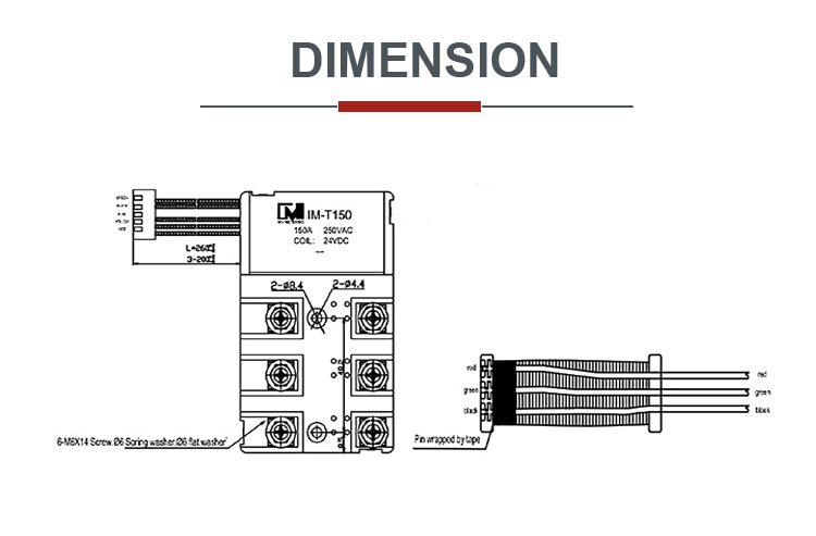
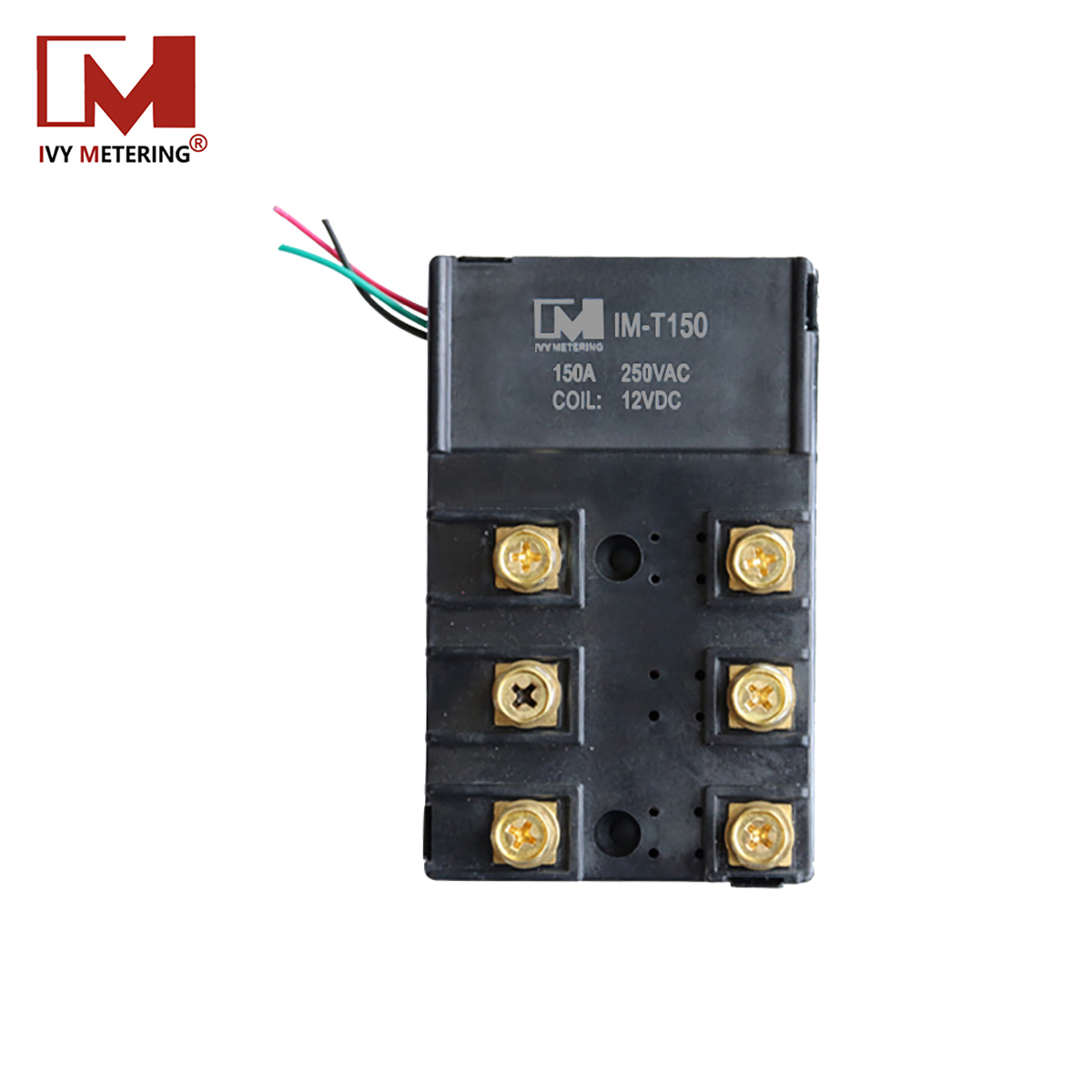
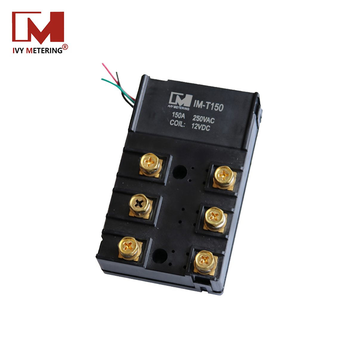
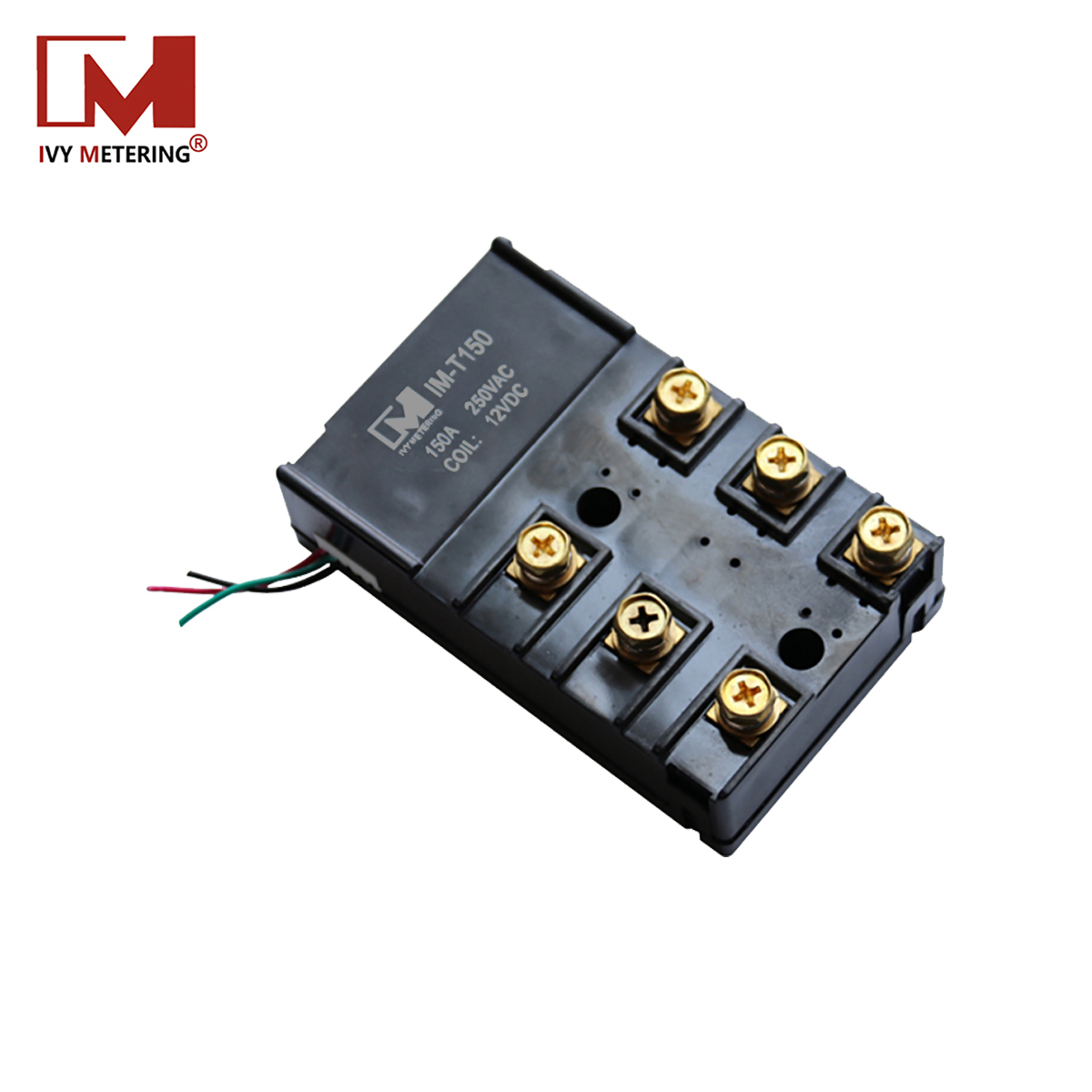
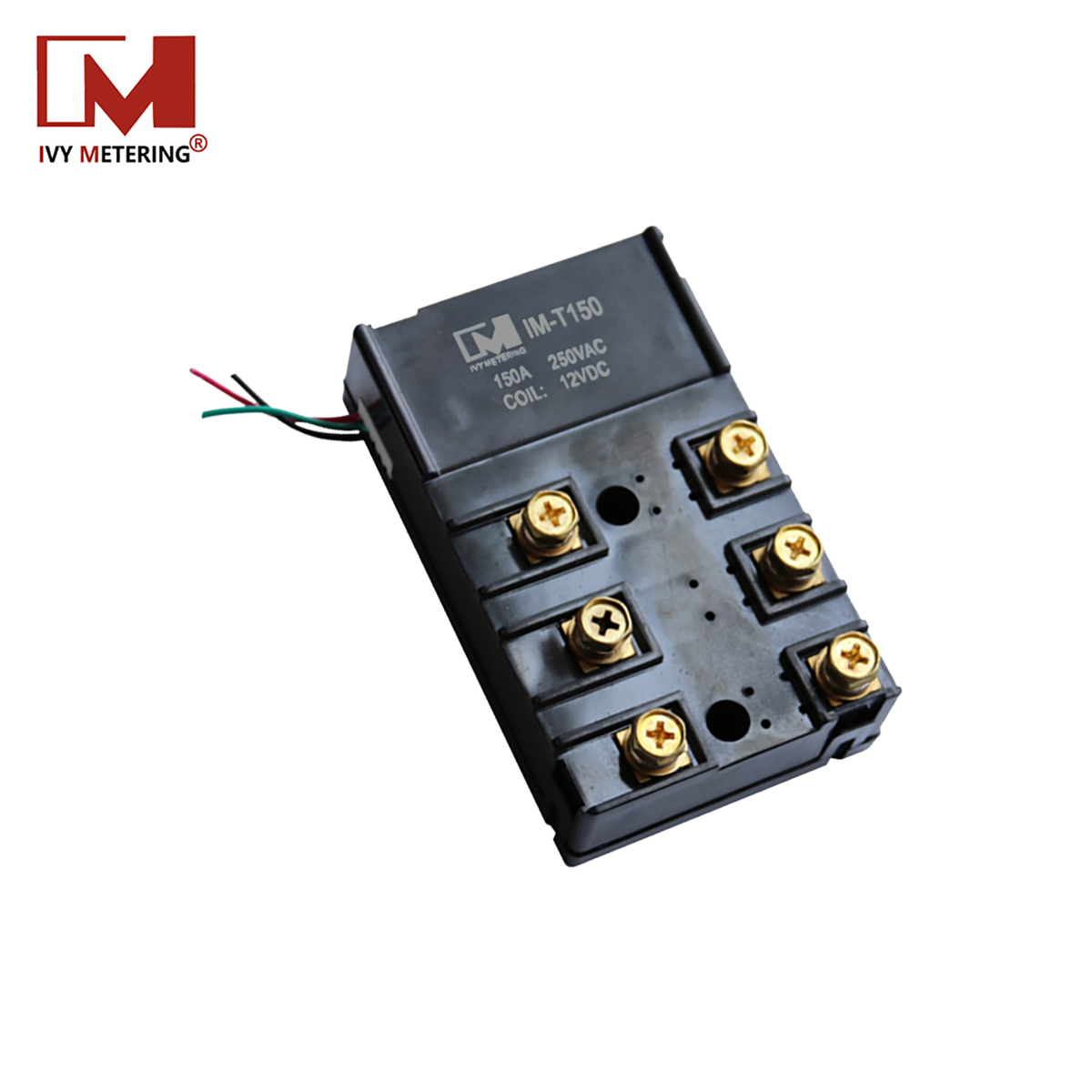
| Dimension (mm) | 110 × 68 × 35 |
| Weight ( g ) | 424 |
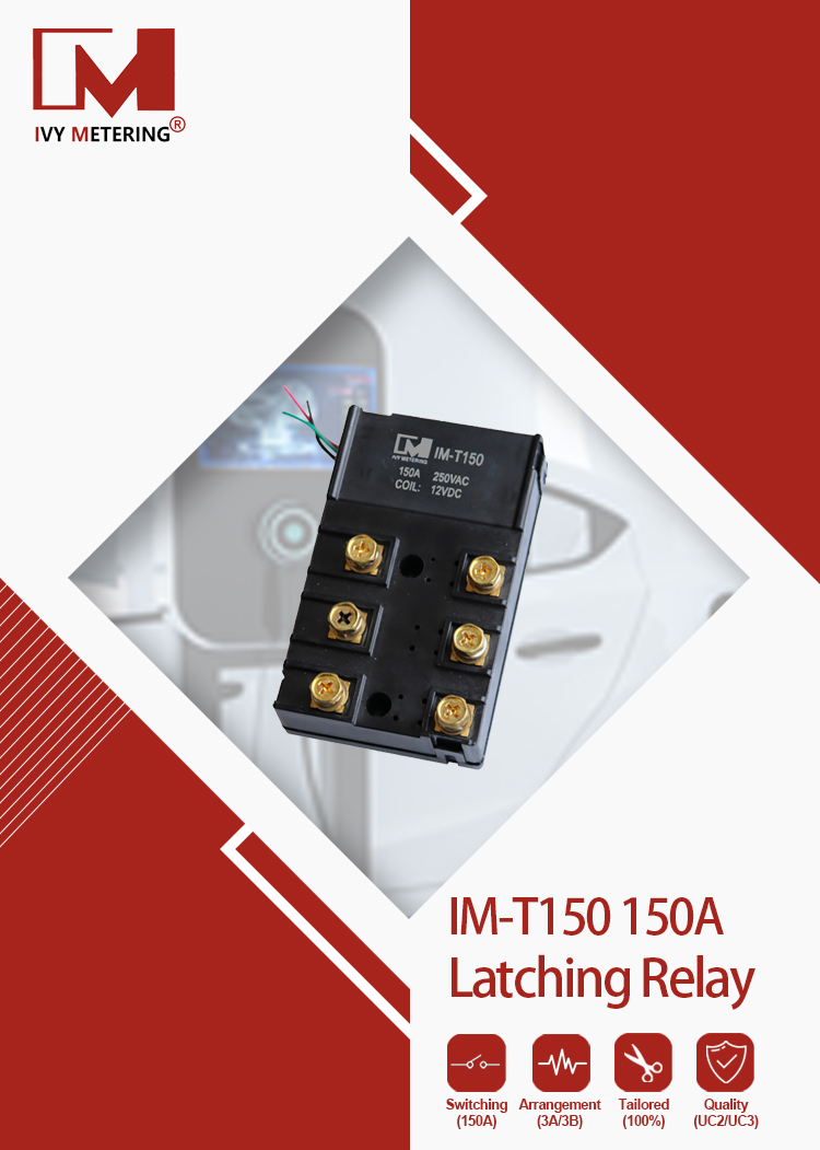
| Contact Arrangement | 3A/3B |
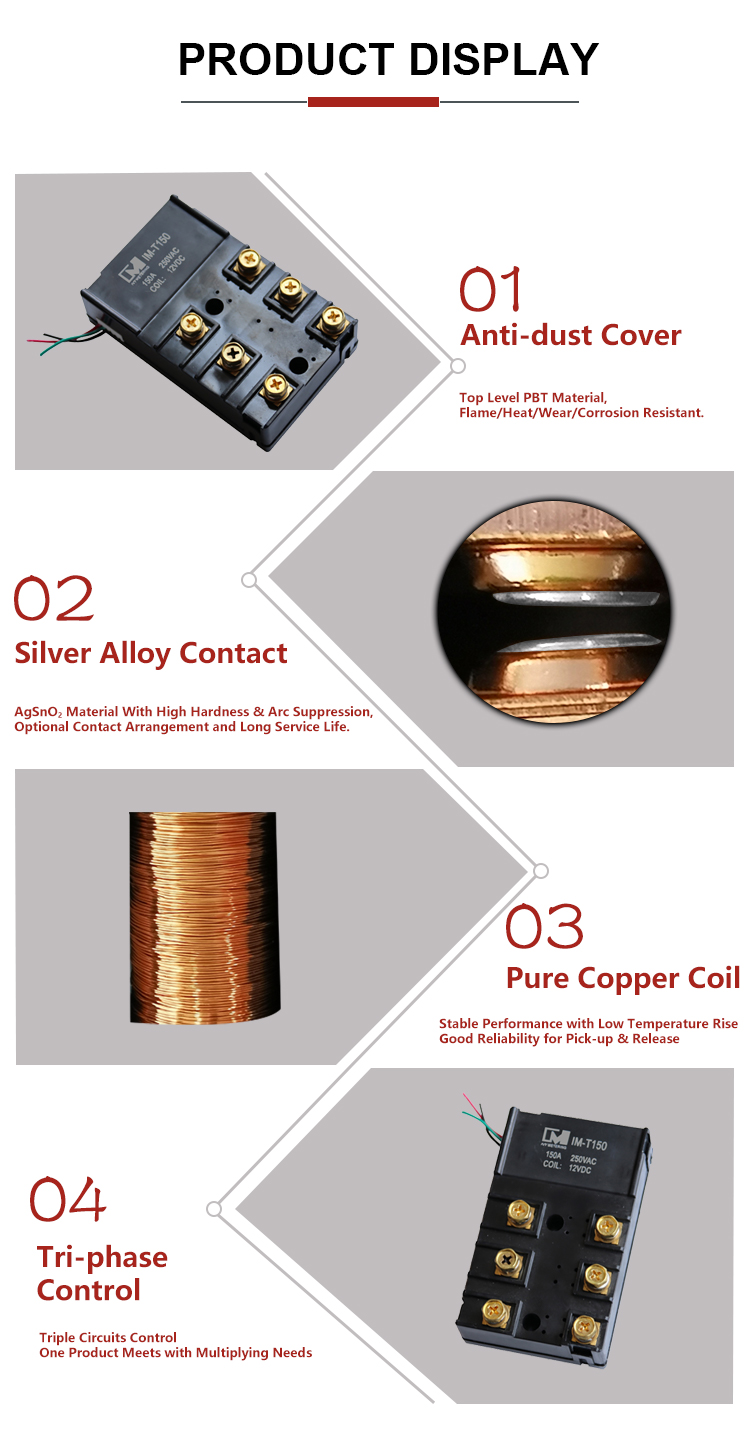
| Contact Material | AgSnO2 |
| Ambient Temperature | -40 ~ 70 ℃ |
| Ambient Humidity | 45% ~ 90% RH |
| Vibration | 10 ~ 55Hz, 1.5mm (DA) |
| Specification Data | |
| Nominal Voltage | 6 ~ 48VDC |
| Power Consumption | Single Coil: 3.0W, Dual Coil: 6.0W |
| Max. Switching Voltage | 250VAC |
| Max. Switching Current | 150A |
| Max. Switching Power | 37500 VA |
| Contact Resistance | < 2.0 mΩ |
| Insulation Resistance | 1000MΩ (DC 500V) |
| Dielectric Creepage | 8 mm |
| Dielectric Strength (Across Open Contact) | > 2000VAC 1min |
| Dielectric Strength (Coil to Contact) | > 4000VAC 1min |
| Electrical Life | 10,000 cycles |
| Mechanical Life | 100,000 cycles |
| Picking-up & Release Time | ≤ 50ms |
| Pulse Duration | 100 ms |
| Functional Shock Resistance | 10G |
| Destructive Shock Resistance | 100G |